GIS Image
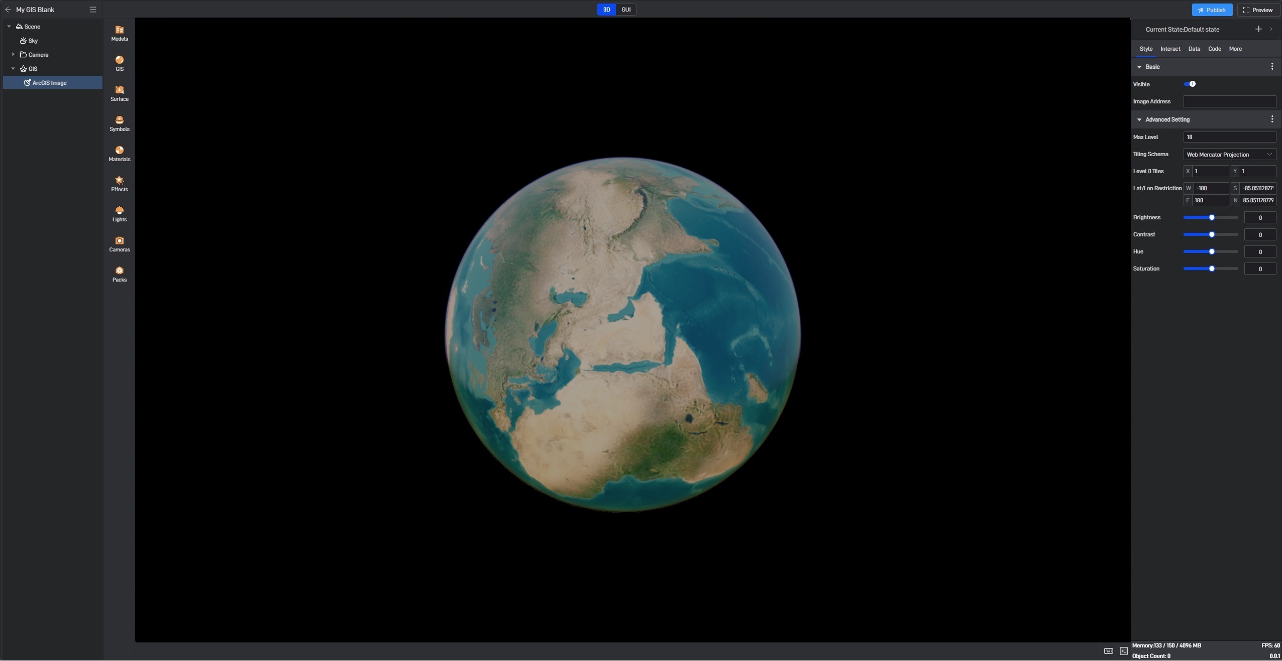
The GIS Image component is one of the components in Wings Engine. It needs to be manually added and can also be removed. In the layer list, imagery with lower order in the sequence will be overlaid on top of imagery with higher order.
1. Add GIS Image
Wings Engine currently provides a default GIS image. Click on GIS, and you can open the GIS image view:
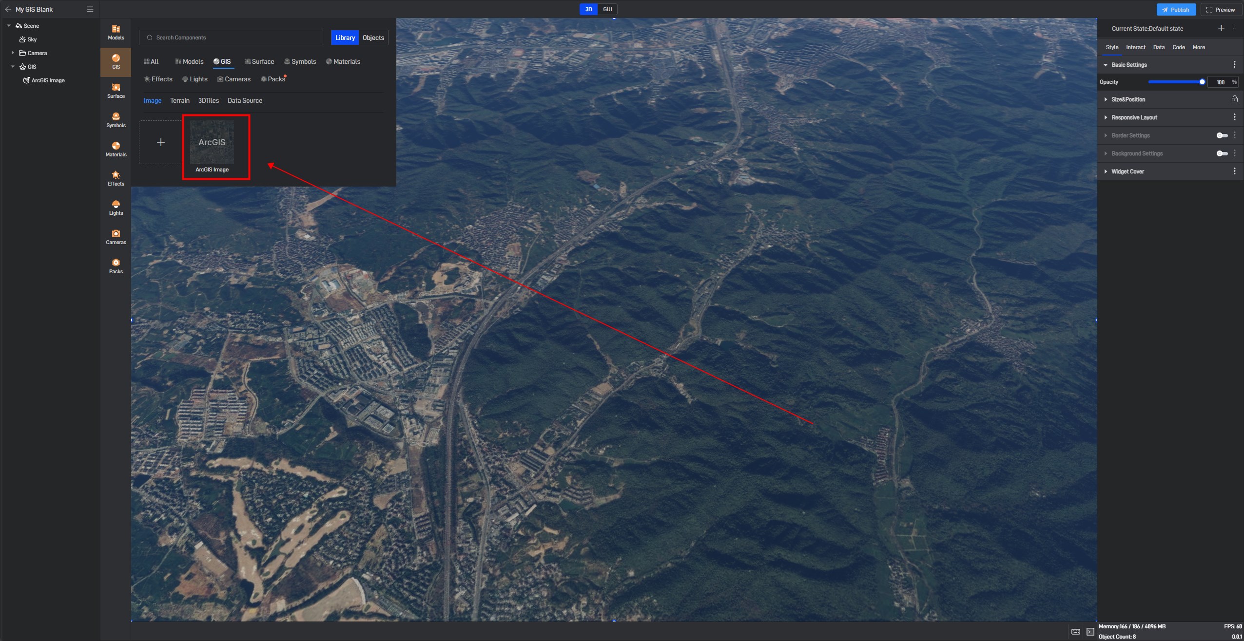
You can also click the “+” sign to add your own GIS image. Wings Engine’s GIS image supports the following five types of GIS image:

They are: URL, Protocol, ArcGIS, Supermap, and AssetId. Next, we’ll introduce how to connect using some of the more commonly used protocols. Other protocols can also be referred to based on these examples:
1.1 URL
This is a universal URL connection method. When connecting custom protocol imagery, you can use this option as a substitute for other protocols. The URL template supports the following parameter settings (from CesiumJS’s API documentation):
{z}: The level of the tile in the tiling scheme. Level zero is the root of the quadtree pyramid.
{x}: The tile X coordinate in the tiling scheme, where 0 is the Westernmost tile.
{y}: The tile Y coordinate in the tiling scheme, where 0 is the Northernmost tile.
{s}: One of the available subdomains, used to overcome browser limits on the number of simultaneous requests per host.
{reverseX}: The tile X coordinate in the tiling scheme, where 0 is the Easternmost tile.
{reverseY}: The tile Y coordinate in the tiling scheme, where 0 is the Southernmost tile.
{reverseZ}: The level of the tile in the tiling scheme, where level zero is the maximum level of the quadtree pyramid. In order to use reverseZ, maximumLevel must be defined.
{westDegrees}: The Western edge of the tile in geodetic degrees.
{southDegrees}: The Southern edge of the tile in geodetic degrees.
{eastDegrees}: The Eastern edge of the tile in geodetic degrees.
{northDegrees}: The Northern edge of the tile in geodetic degrees.
{westProjected}: The Western edge of the tile in projected coordinates of the tiling scheme.
{southProjected}: The Southern edge of the tile in projected coordinates of the tiling scheme.
{eastProjected}: The Eastern edge of the tile in projected coordinates of the tiling scheme.
{northProjected}: The Northern edge of the tile in projected coordinates of the tiling scheme.
{width}: The width of each tile in pixels.
{height}: The height of each tile in pixels.
Example URL:
http://{s}.basemaps.cartocdn.com/light_all/{z}/{x}/{y}.png
1.2 WMTS Protocol
WMTS is the most widely used base image service and is an OGC standard service. For specific protocol definitions, refer to the OGC official documentation.
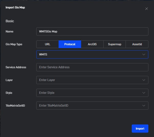
As shown in the diagram, select WMTS when choosing the connection protocol and enter the root directory address of the WMTS service.
After entering the address, Wings Engine will automatically read and parse the Capabilities file. If the address is correct, options for Layer, Style, and TileMatrixSetID will automatically be set according to the options in the Capabilities file.
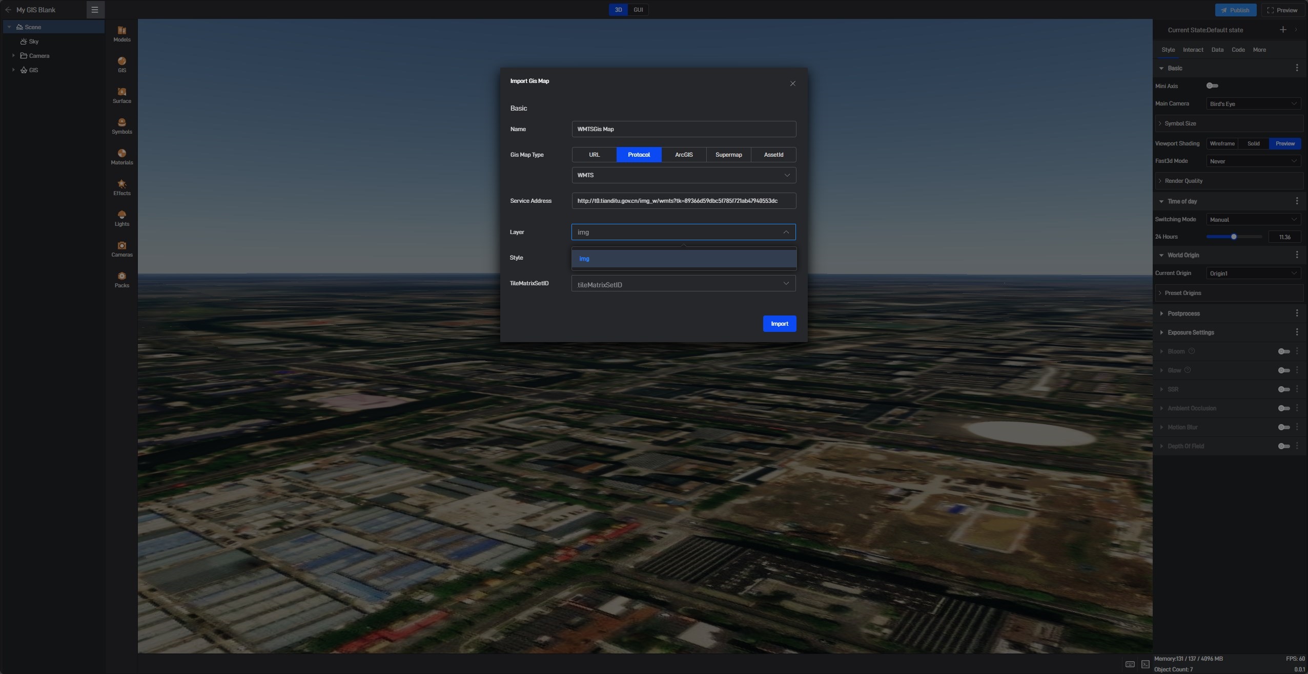
After selecting the appropriate Layer, Style, and TileMatrixSetID:
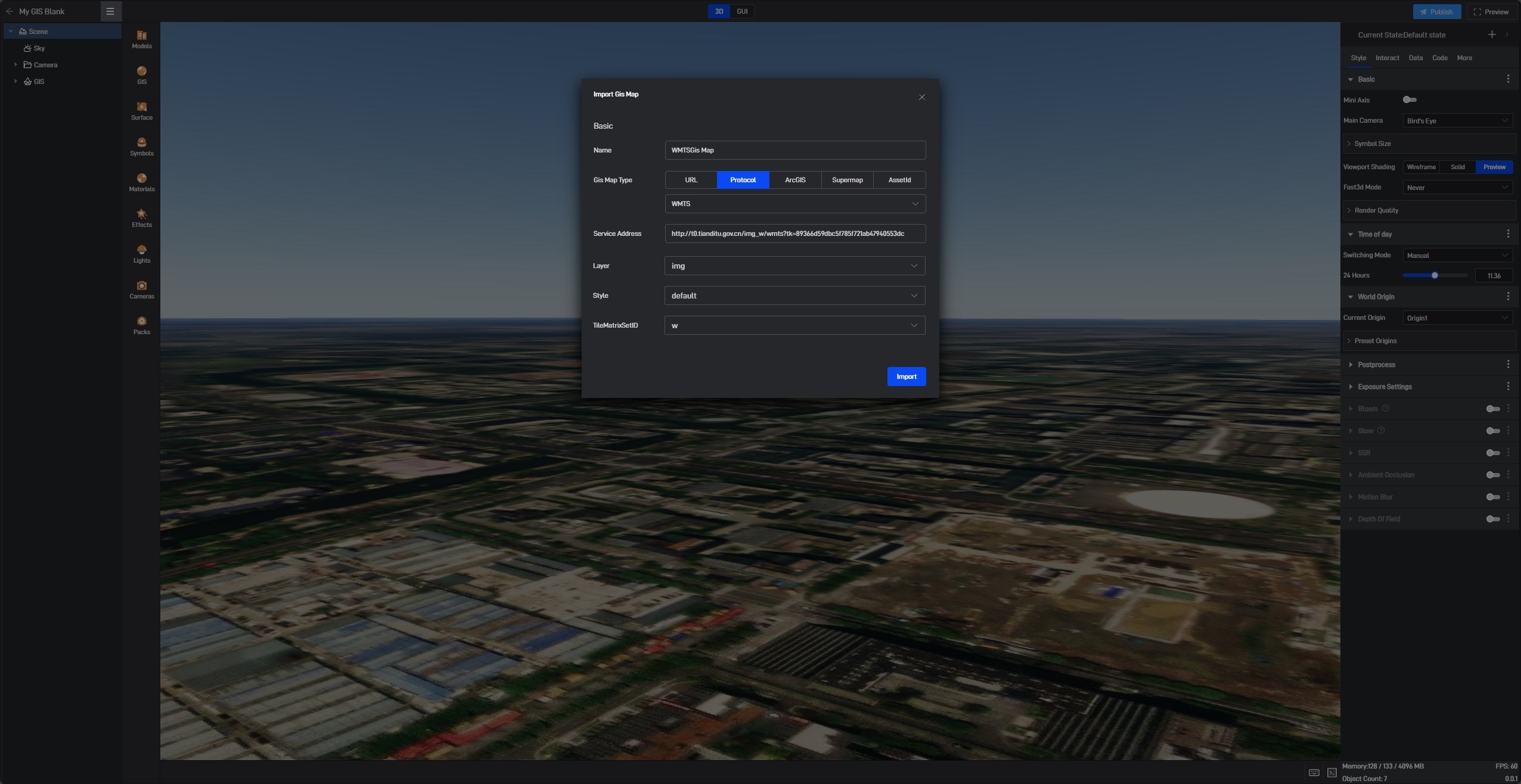
Click Import, and you should see the imagery successfully connected.
Advanced settings in the WMTS protocol, such as maximum level of detail and image tiles, will be automatically read from the Capabilities file, so you don’t need to set them manually.
1.3 SuperMap REST Interface
The integration method for the SuperMap REST interface is similar to WMTS. You need to input the generated service address directly, and Wings Engine will automatically read the options from the address. Here, we use an example address for iServer: http://localhost:8090/iserver/services/map-world/rest
After selecting the directory and resources, adjust the advanced settings as needed. You can refer to the content in Section 2.2 Advanced Settings for detailed information. Once the settings are complete, click “Import” to finish the integration of the SuperMap REST interface.
2. Image Settings
The settings for the GIS image component** **are generally divided into two categories: Basic Settings and Advanced Settings. Below is a detailed introduction:
2.1 Basic Settings
| ** Configuration item ** | Describe |
|---|---|
| Visibility | Whether to display the GIS image |
2.2 Advanced Settings
| ** Configuration item ** | Describe |
|---|---|
| Maximum Level of Detail | The higher the level of detail, the richer the GIS image display, but it requires more performance. Typically, levels 16-18 are used. A level of detail that is too small can make the GIS image blurry, while a level that is too high can slow down image loading. |
| image Tile Format | You can select the image tile format for the GIS image as either “Web Mercator Projection” or “Plate Carree Projection”. |
| Longitude and Latitude Restrictions | The GIS image will only be displayed within the specified longitude and latitude restriction area. When selecting Web Mercator Projection, the latitude restrictions will automatically be set to 85 degrees north and south. |
| Brightness | Adjust the overall brightness of the GIS image. |
| Contrast | Adjust the overall contrast of the GIS image to make black and white colors more distinct. |
| Hue | Adjust the overall hue of the GIS image, making it lean towards red or green. |
| Saturation | Adjust the overall saturation of the GIS image, making the colors more muted or more vibrant. |