Overview of Markers
1. Introduction to Markers
In smart campus or smart city projects, markers are a commonly used feature and one of the most frequent methods of interacting with data.
Markers are divided into two types: free markers and data markers. The distinction between these two types is based on the method of addition. Markers added manually and can be moved are called free markers, while those added through data, such as latitude and longitude or XYZ coordinates, are called data markers.
2. Marker Style Settings
2.1 Adding Markers
2.1.1 Adding Free Markers
In the scene editing interface, click on “Symbols” in the left-hand menu. After expanding it, you will see several preset free marker styles under “Markers.”
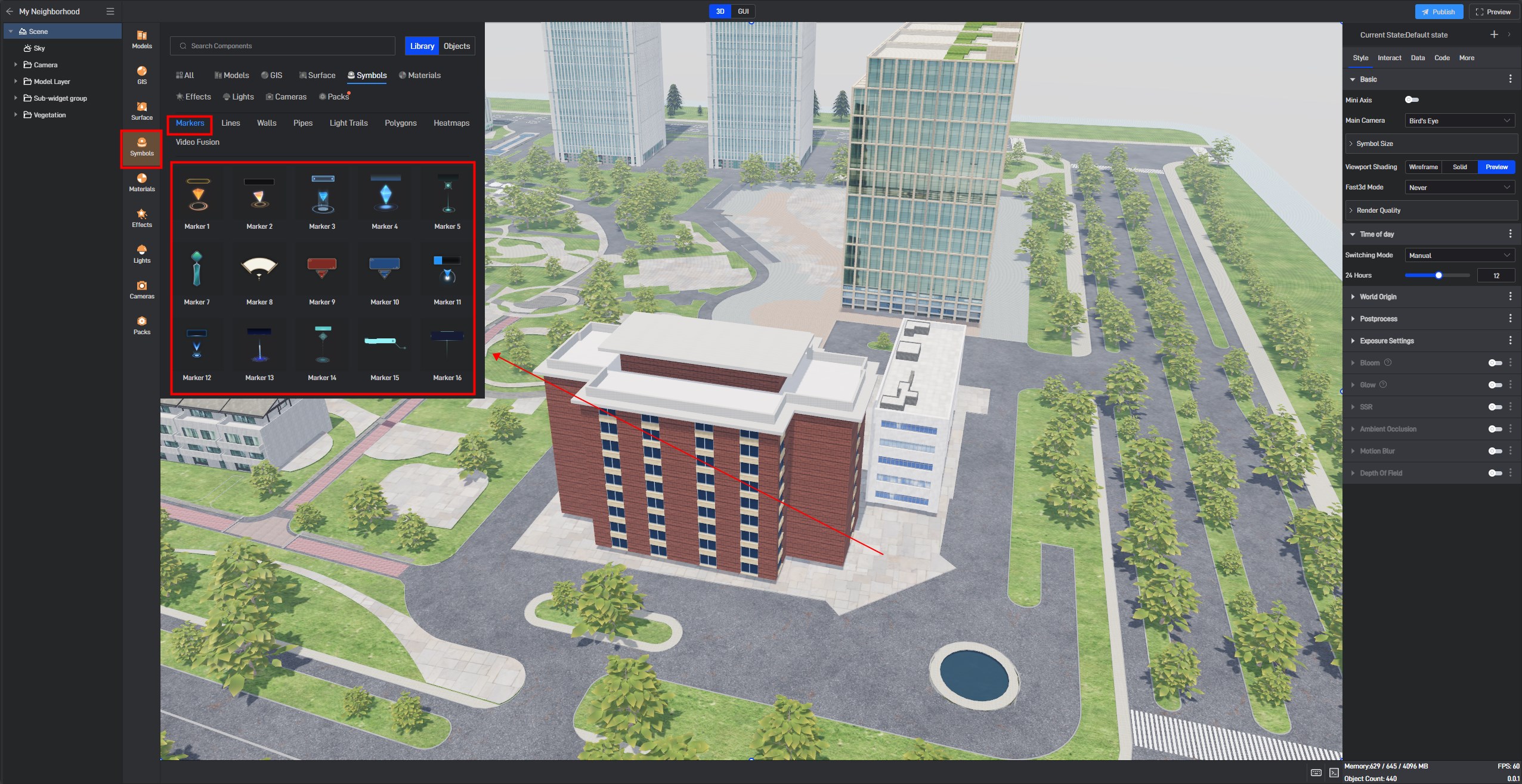
Select one of the marker styles and add it to a floor in the scene:
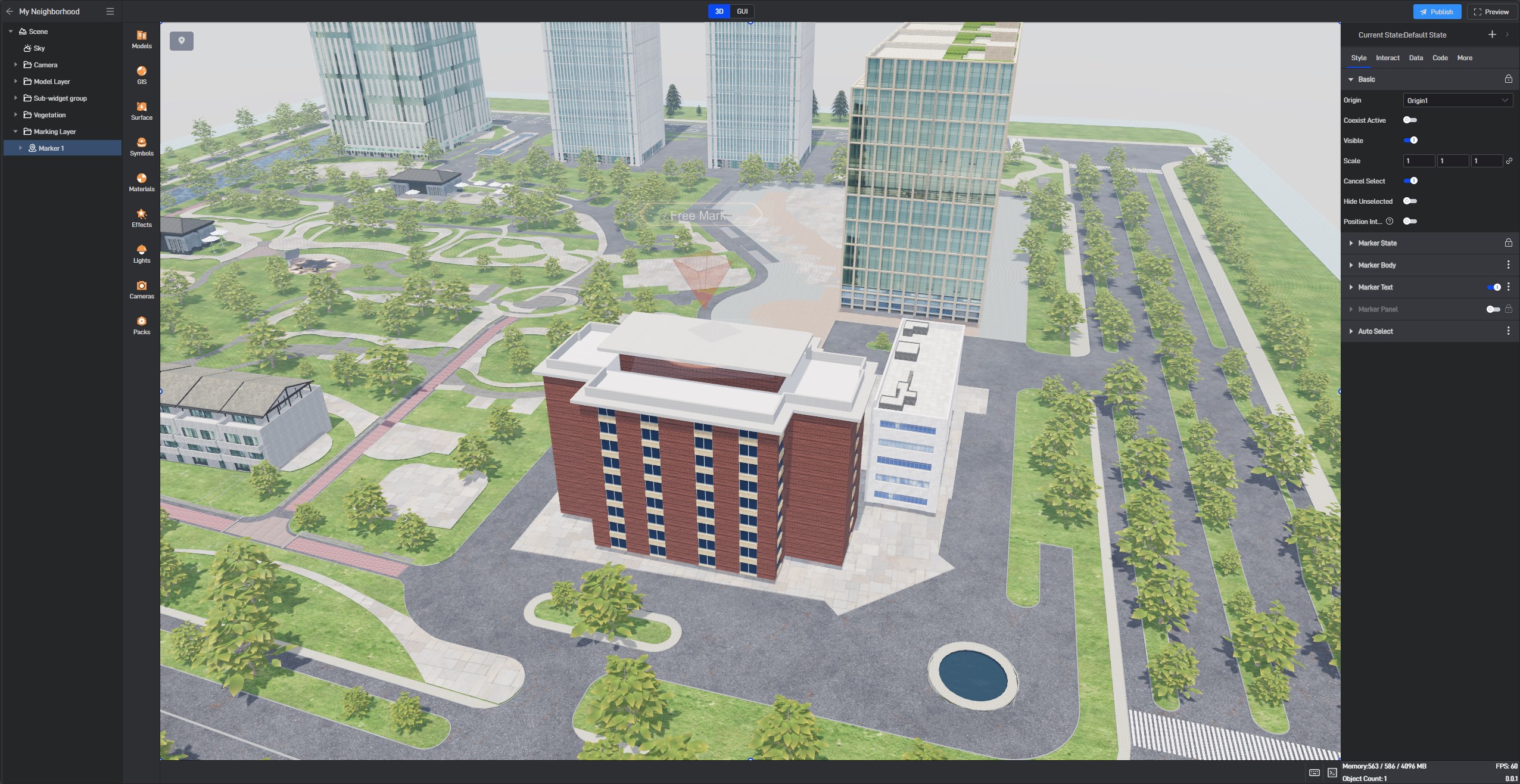
You can see that the added marker in the model automatically forms a marker group in the left-side component layer. When we add a marker in the scene, we are essentially adding a marker group. A marker group is a combination of a set of markers, which can have their interactions universally set, such as pop-ups, highlighting, etc.
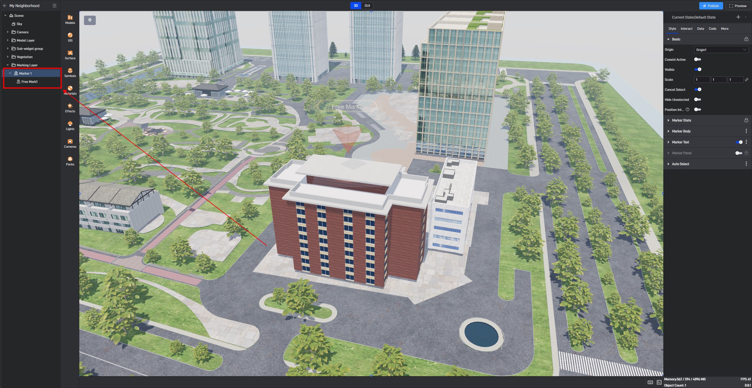
When the marker group is selected, a symbol will appear in the upper left corner of the scene editing interface. Clicking this symbol allows you to continue adding marker styles from the marker group in the scene.

2.1.2 Data Markers (Spatial Coordinate System)
When we need data linkage or data filtering, free markers alone are insufficient. We need to convert free markers into data markers. In this case, we can first select all the free markers, right-click and choose “Copy Data”:
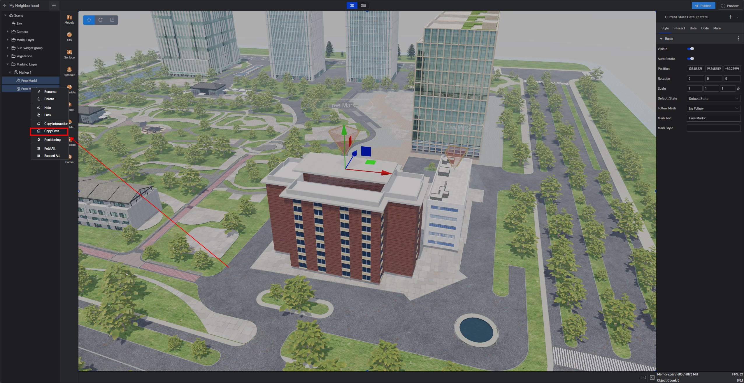
Then, create a new Excel file and press Ctrl+V:
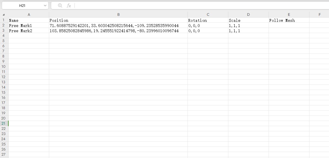
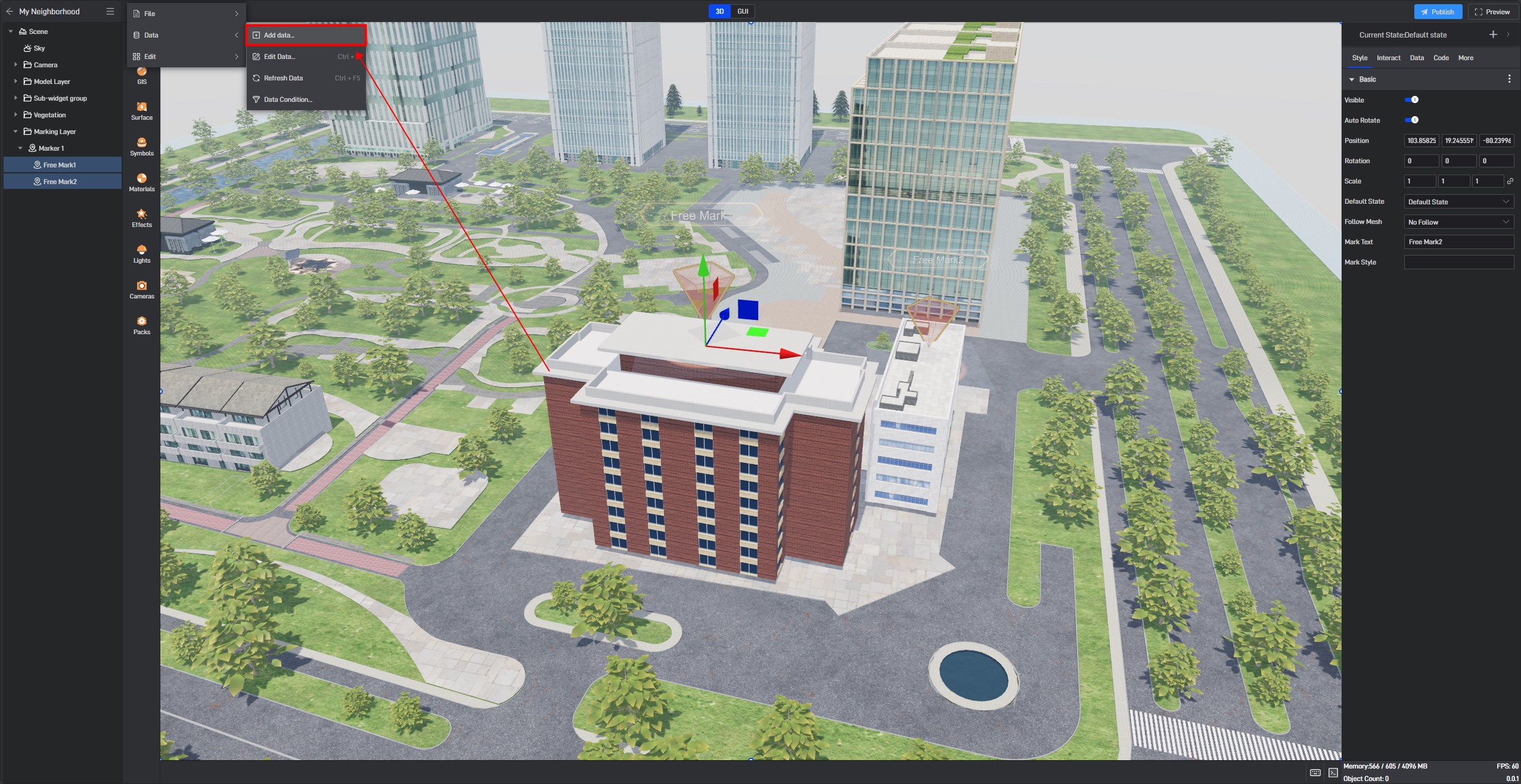
Save this Excel file as sample data, then click “Add Data” under the Data menu in the top left corner of Wings Engine to add a data source to the project..
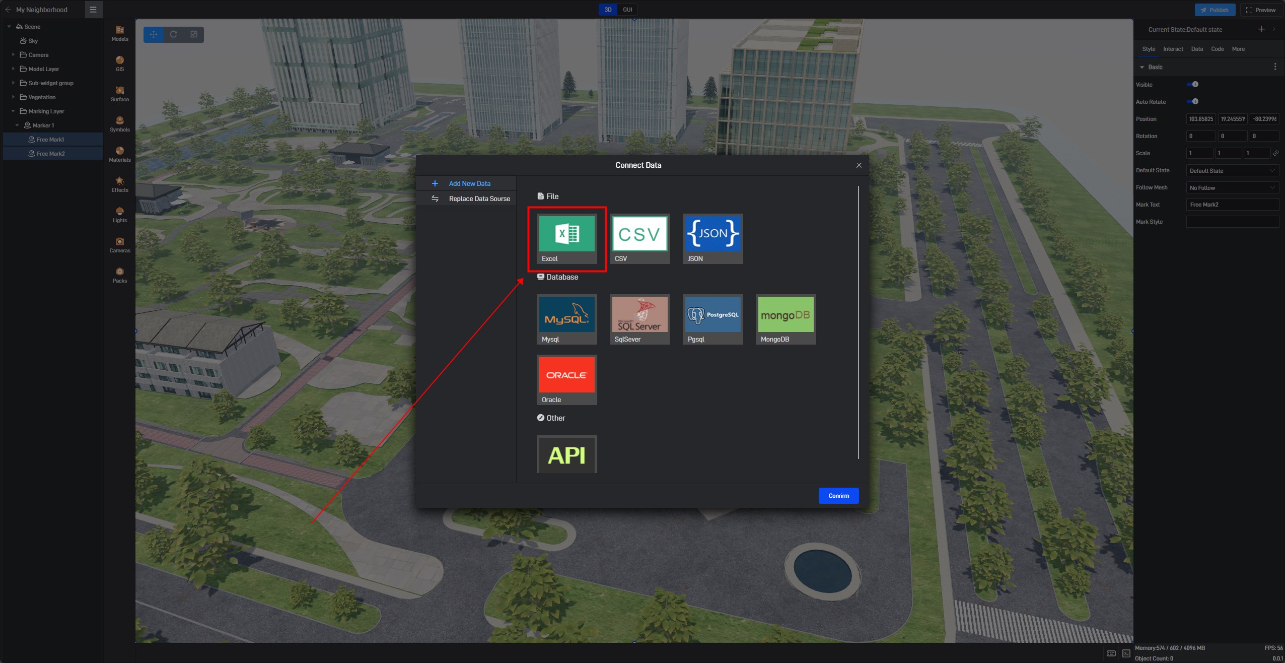
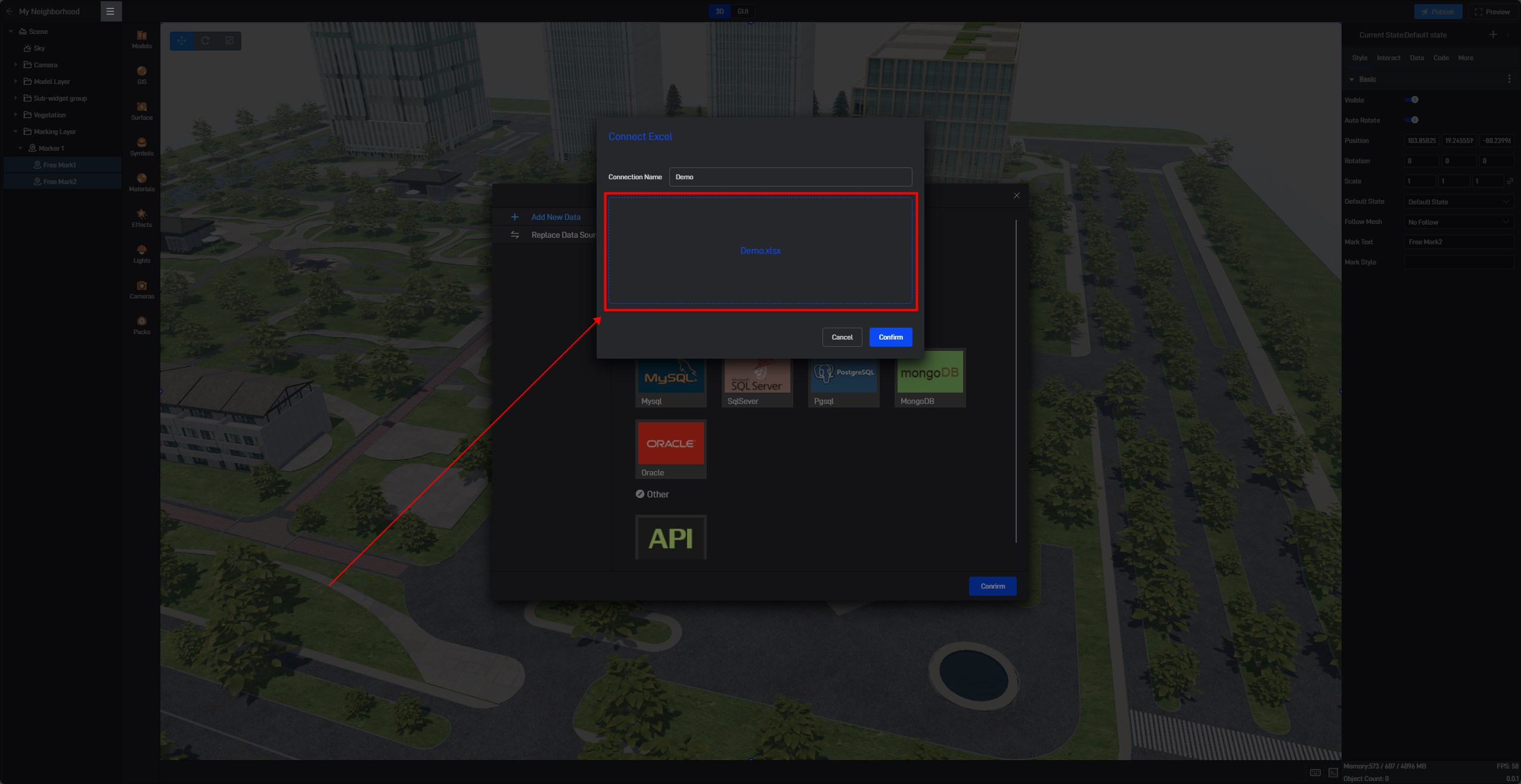
With the data successfully imported, the copied data are all in a spatial rectangular coordinate system. Therefore, in the top right corner, select the data column and change the coordinate type to spatial coordinates. Then, fill in the fields of name and position according to the labels in the data. It’s important to note that the Marker Key also needs to be entered. The Marker Key is used to compare each data marker itself when data changes, so it must be set to a non-repetitive field. If the names are unique, it is recommended to use the name as the Marker Key; otherwise, it’s advisable to assign a unique ID to the marker as the Marker Key.
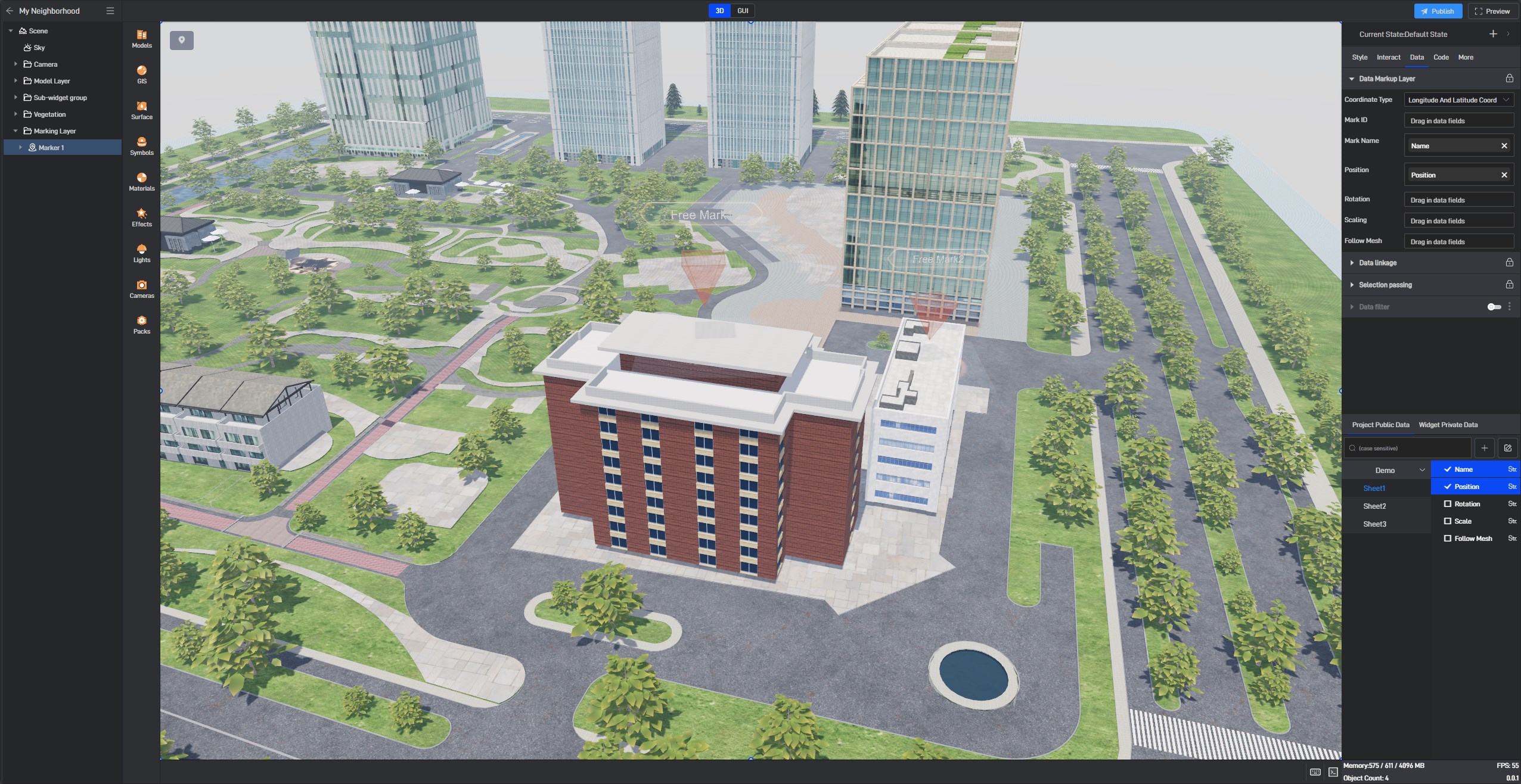
After setting, delete the original free markers. Now, the data markers have been added, and the free markers have also been converted to data markers. We can further set data linkage and data filtering based on this:
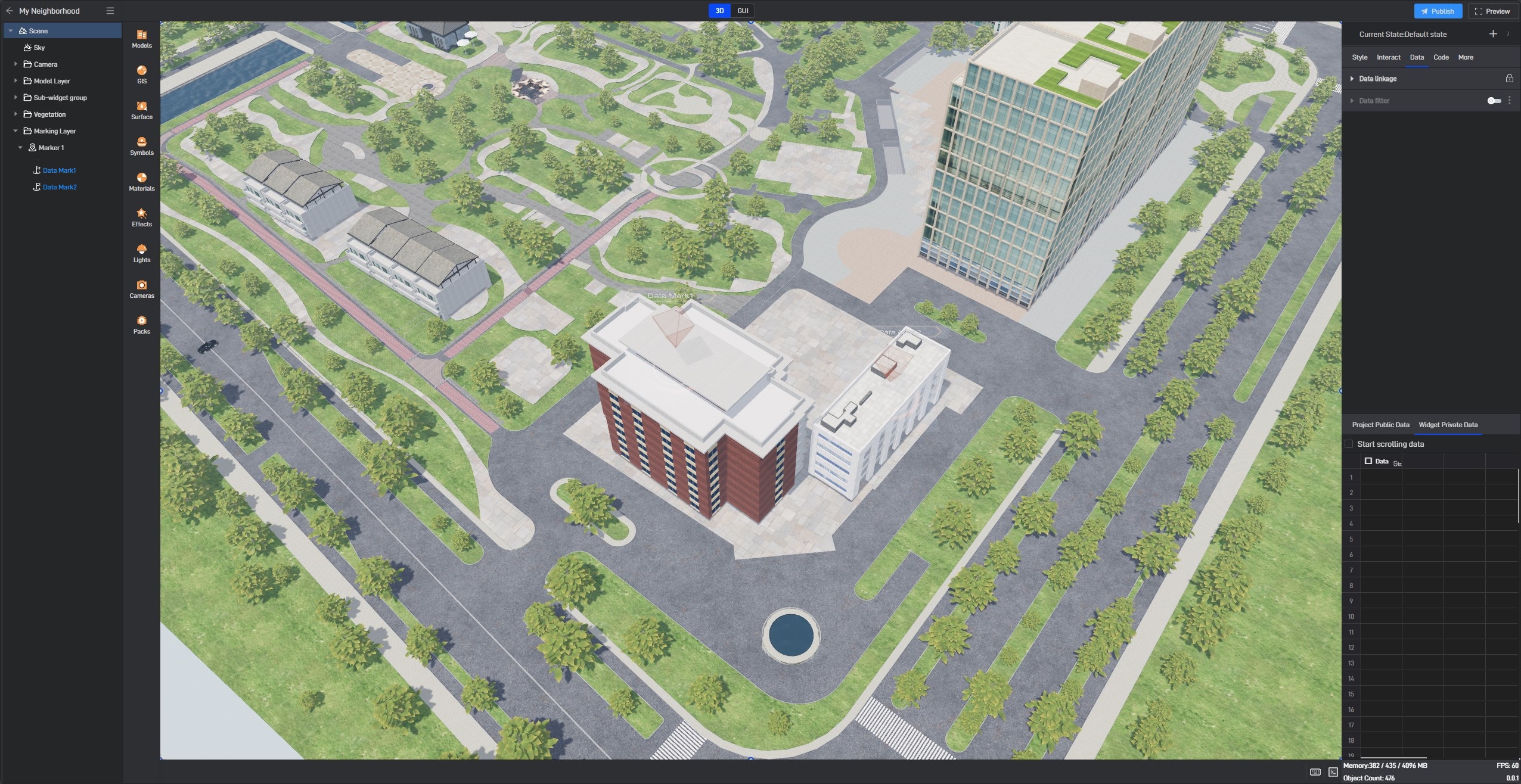
Note that the position can also be directly copied from the imported element model, with the operation being the same as copying the position of a marker.
It’s worth mentioning that this Excel file can also be replaced with an API or database, allowing the marker’s name, position, and quantity to be dynamically generated based on the data.
2.1.3 Data Marking Points (Latitude and Longitude Coordinate System)
Latitude and longitude data are generally collected by GPS devices (or Beidou devices). Typically, we need to organize the data into the following format:
| ID | Name | Position |
|---|---|---|
| 1 | Marker1 | 120.0001,30.2801,5.1 |
| 2 | Marker2 | 120.0002,30.2802,5.1 |
| 3 | Marker3 | 120.001,30.2799,5.1 |
| 4 | Marker4 | 119.999,30.280,5.1 |
The location consists of three values: longitude, latitude, and altitude, separated by commas. **Please note, the comma must be an English comma. **
After importing this data, select the marking point group, and drag the data fields into the corresponding data items. You will see that the marking points are automatically generated, as shown below:
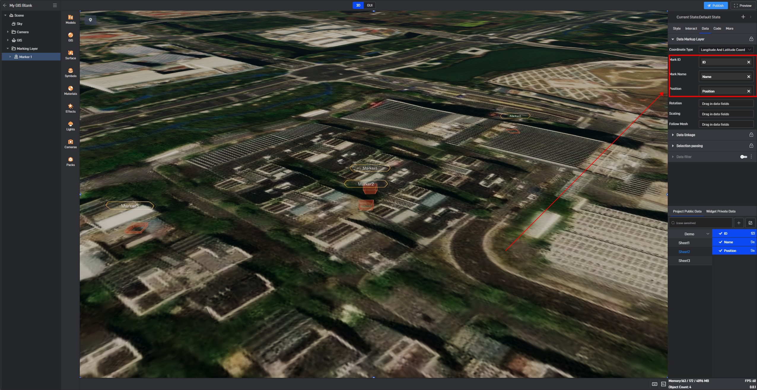
If there is an obvious positional deviation, please select an appropriate origin coordinate based on the coordinates of the marking point:
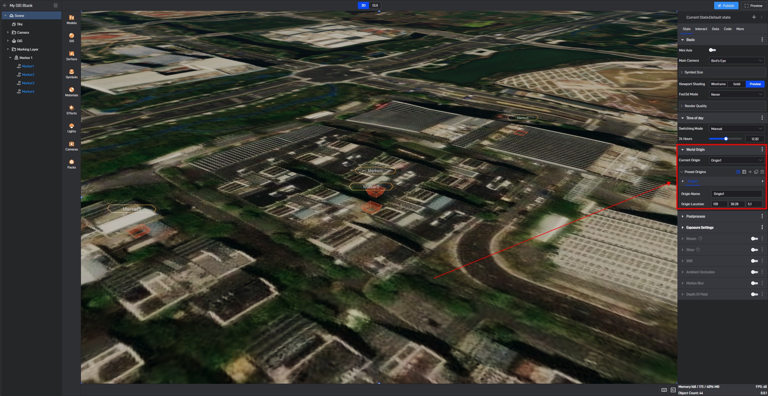
2.2 Marker Style Settings
When setting marker styles, it is done uniformly on the marker group, and interactions are also set uniformly on the marker group. All markers under the marker group share the marker group’s style and interaction.
The following is an explanation of these configuration items:
2.2.1 Basic Settings
| ** Configuration item ** | Describe |
|---|---|
| Origin | The origin of the marking model, consistent with the model setting origin. |
| Coexist Active | Set whether multiple marking points can be selected simultaneously. |
| Visible | Set whether to show the marking points. |
| Scale | Size scaling of the marker group. |
| Cancel Select | Set whether to allow deselection by clicking again when in the selected state. |
| Hide Unselected | Set whether to hide other marking points when a marking point is selected. |
| Position Interpolate | Disabled by default, indicates whether to apply interpolation animation when the generated marking position changes. |
2.2.2 Marker Status
In the marker status, you can set the appearance of the marking points when they are in selected or hovered states.
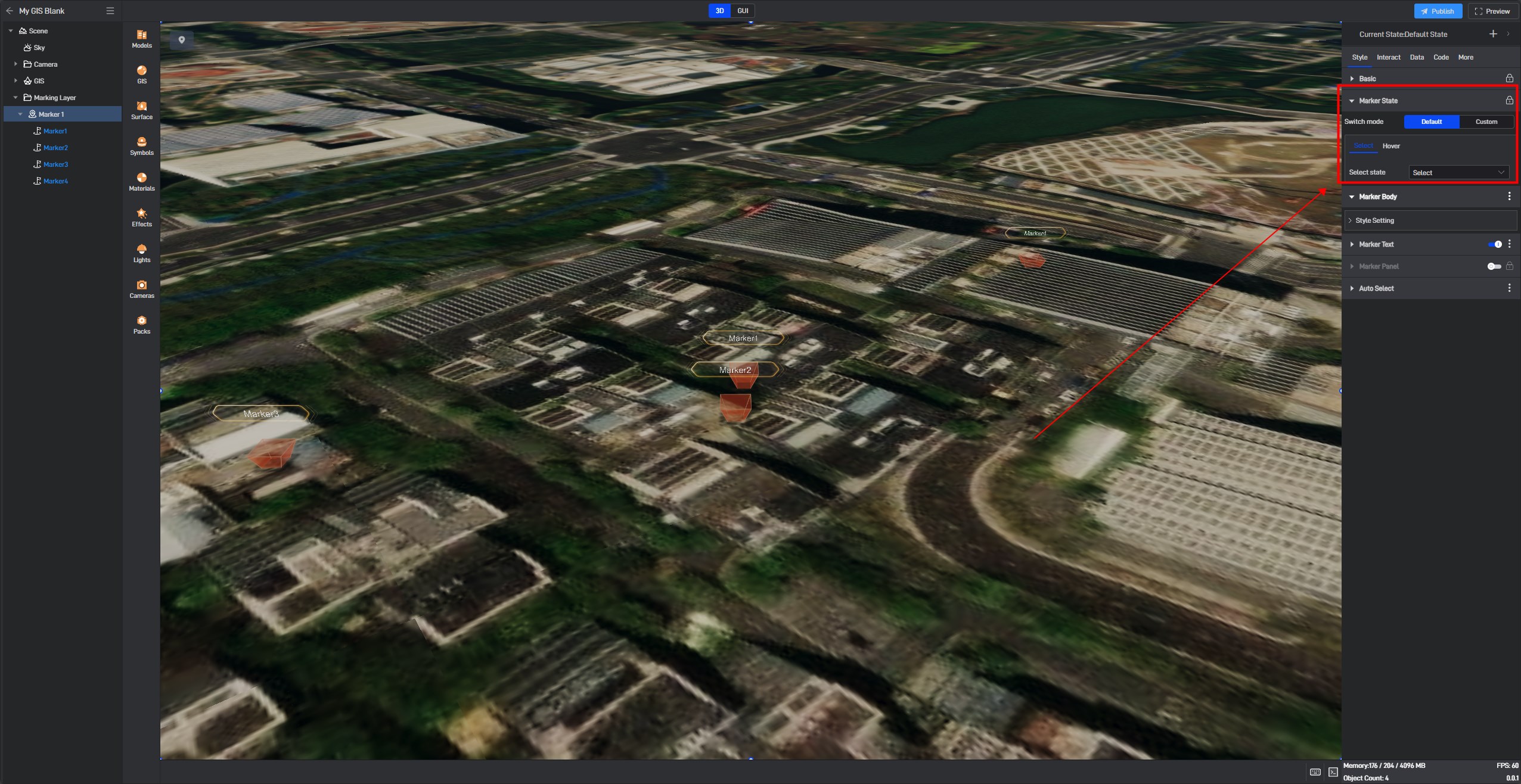
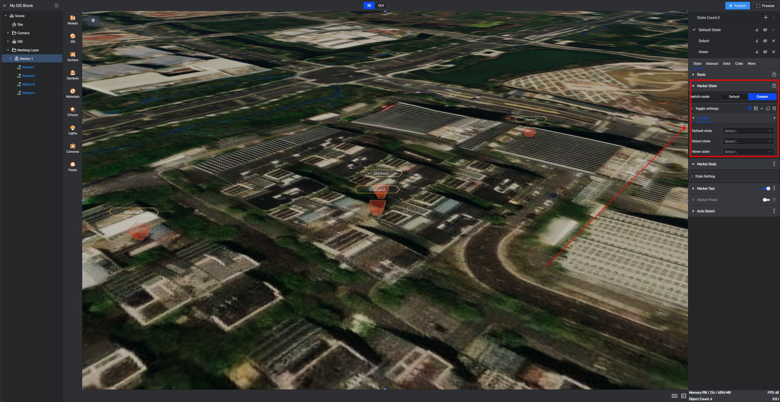
You can also create multiple configurations through custom options, where each configuration can set the appearance of the marking points in default, selected, and hovered states.
2.2.3 Marking Subject
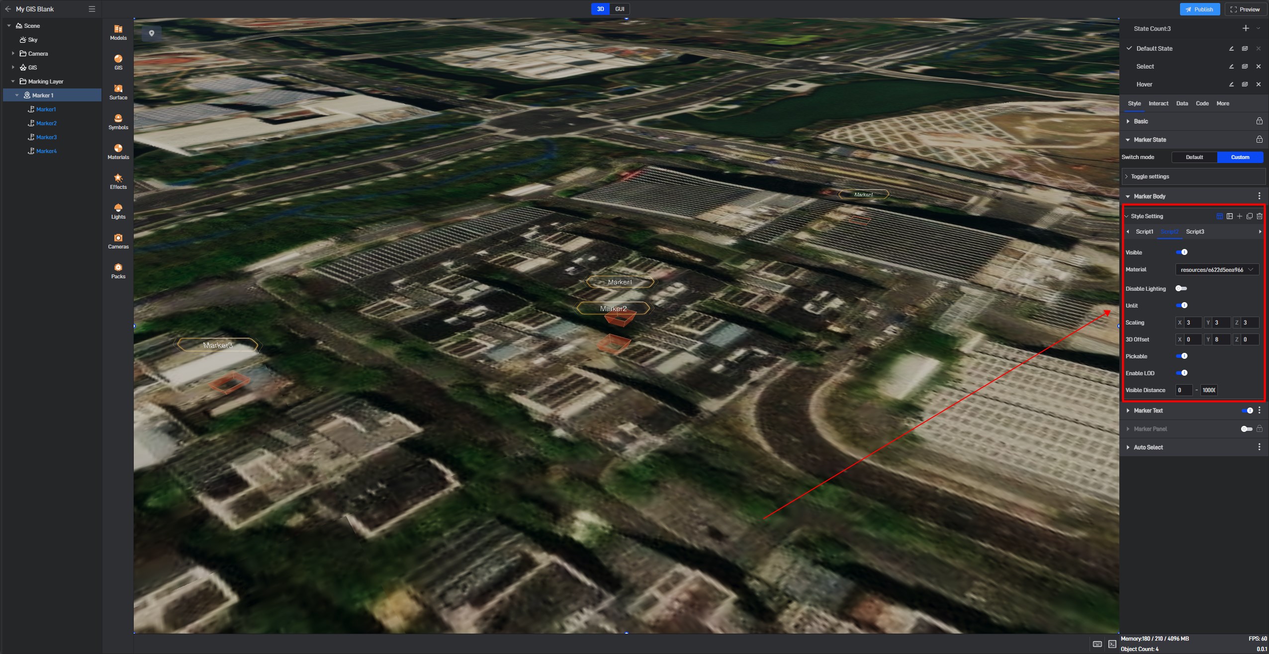
The marking subject refers to the components of a marking point. Within the marking subject, the style of the marking point can be configured.
Each preset style of a marking point is set with different states by default, divided into three types: “Default state, Selected state, and Hover state“. If you need to modify the preset marking point style, it needs to be modified under the corresponding state.
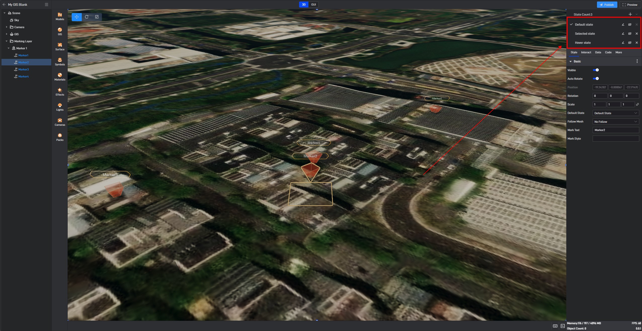
We can see that different configuration items in the marking subject may vary due to the use of different materials. The materials for the subject are generally divided into two categories: one is two-dimensional material, such as videos and images; the other is three-dimensional material, mainly referring to models.
Configuration items for the marking subject will differ based on the added materials.
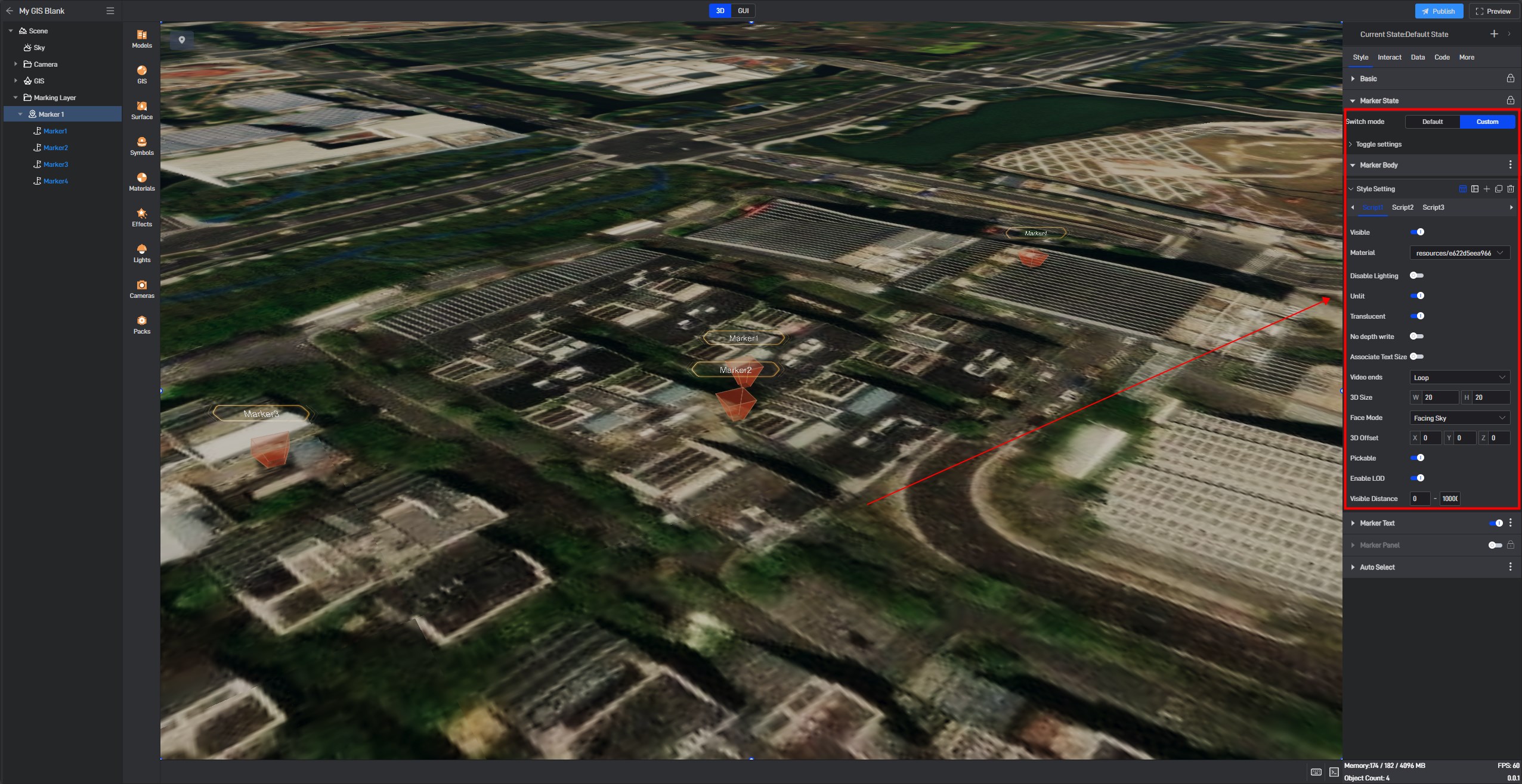
Additionally, the number of configuration items for the marking subject will also vary depending on the complexity of the marking point style. The more complex the marking point style, the more configurations there will be for the marking subject.
For example, a regular marking point consists of only one marking point model, with just one configuration item.
The preset style of Marking 1 consists of three parts: the marking point model, the marking point base, and the text box, so there will be three configuration items in the configuration.

Below, we will introduce these configuration items based on the different materials of the marking point:
Two-Dimensional Material
| ** Configuration item ** | Describe |
|---|---|
| Visible | Set whether to display the marking point. |
| Material | Two-dimensional materials mainly include images and videos. Image formats are primarily png, jpg, and video formats are usually webm. |
| Disable Lighting | Whether to disable the influence of lighting. |
| Unite | The marking material will default to reflect ambient light, and this is enabled by default. |
| Translucent | Whether the marking point material is “semi-transparent”. This is usually enabled in digital twin scenes. |
| No Depth write | Whether to exclude the material depth from the value range, enabled by default. |
| Associate with Text Size | Whether the material size is associated with the marking text size, disabled by default. |
| Video Ends | When the material is a video, the state after the video finishes playing. You can choose “loop playback, stop at the end, or return to a specified second at the end”. If you choose to return to a specified second, you can set the specific time. |
| 3D Size | The size of the material in the plane, which can be set according to needs. |
| Face Mode | The orientation of the material in three-dimensional space, you can choose “normal, facing upwards, vertically facing the camera, always facing the camera”, and select according to your needs. |
| 3D Offset | The degree of offset relative to the 3D origin of the marking point in a 3D scene. |
| Pickable | Whether the marking point in the scene can be selected with the mouse, enabled by default. |
| Enable LOD | Whether to enable the marking point visibility distance in the scene, enabled by default. |
| Visible Distance | The visible distance of the marking point in the scene, you can set the visible distance range by yourself. |
Three-Dimensional Material
| ** Configuration item ** | Describe |
|---|---|
| Visible | Set whether to display the marking point. |
| Material | The 3D material for the marking point subject is the model material. The supported model material formats are consistent with those supported by the software. |
| Disable Lighting | Whether to disable the influence of lighting. |
| Unite | The marking material will default to reflect ambient light, and this is enabled by default. |
| Scaling | The scaling ratio of the model in the 3D space, which can be set according to the size of the marking point model. |
| 3D Offset | The degree of offset relative to the 3D origin of the marking point in a 3D scene. |
| Pickable | Whether the marking point in the scene can be selected with the mouse, enabled by default. |
| Enable LOD | Whether to enable the marking point visibility distance in the scene, enabled by default. |
| Visible Distance | The visible distance of the marking point in the scene, you can set the visible distance range by yourself. |
2.2.4 Marking Text
This refers to the marking point text style, and setting the text style here will apply to all marking points within the marking group.
| ** Configuration item ** | Describe |
|---|---|
| Color | The font color of the marking text, which can be set according to needs. |
| Unite | The marking material will default to reflect ambient light, and this is enabled by default. |
| Font Size | The font size of the marking text, which can be set according to the needs of the marking point. |
| Arrangement | The text alignment method, which can be set to horizontal or vertical alignment. |
| Face Mode | The orientation of the marking text in three-dimensional space, you can choose “normal, facing upwards, vertically facing the camera, always facing the camera”, and select according to your needs. |
| 3D Offset | The degree of offset relative to the 3D origin of the marking point in a 3D scene. |
| Enable LOD | Whether to enable the marking point visibility distance in the scene, enabled by default. |
| Visible Distance | The visible distance of the marking point in the scene, you can set the visible distance range by yourself. |
2.2.5 Marking Panel
The marking panel is mainly used for setting the interactive popup window for marking points. When we need to click on a marking point to display a popup window, it can be set here.
| ** Configuration item ** | Describe |
|---|---|
| Select Popup | When you need to set the interaction between the marking point and the popup window, you can select the popup window added in the project here. |
| Show Dimensions | The display mode of the popup window, which can be set to 2D or 3D display. |
| 3D Size | The size of the popup window, the size set here is not related to the size of the popup window set in the project. |
| 3D Offset | The degree of offset relative to the 3D origin of the marking point in a 3D scene. |
| Face Mode | The orientation after the popup window is displayed. You can choose “normal, facing upwards, vertically facing the camera, always facing the camera”, and select according to your needs. |
| Priority | The interaction display order after clicking the marking point. When the priority is 1, the popup window content will be displayed first. |
| Show Mode | The display style after the popup window is displayed. You can choose “show all, carousel display, hover display, click display”. |
| Connect Line segment | When enabled, a line segment will connect the popup window to the marking point when the popup window appears. |
| Synchronous Click and Hover | Disabled by default. When enabled, hovering the mouse over the popup window can also trigger corresponding events. |
2.2.6 Auto-Select
In “carousel” mode, after enabling “play animation”, the marking points will automatically be selected in sequence according to the order they were added. You can enable “loop playback” and set the “carousel interval” for marking points.

In “distance detection” mode, after enabling “detection”, selecting “detection object” and setting the detection “distance”, when the “detection object” moves within the scene and enters the detection “distance” of a marking point, that marking point will be selected.
